<kaz at kylheku
dot com>| Date |
Notes |
|---|---|
| December 2, 2012 |
Initial revision. |
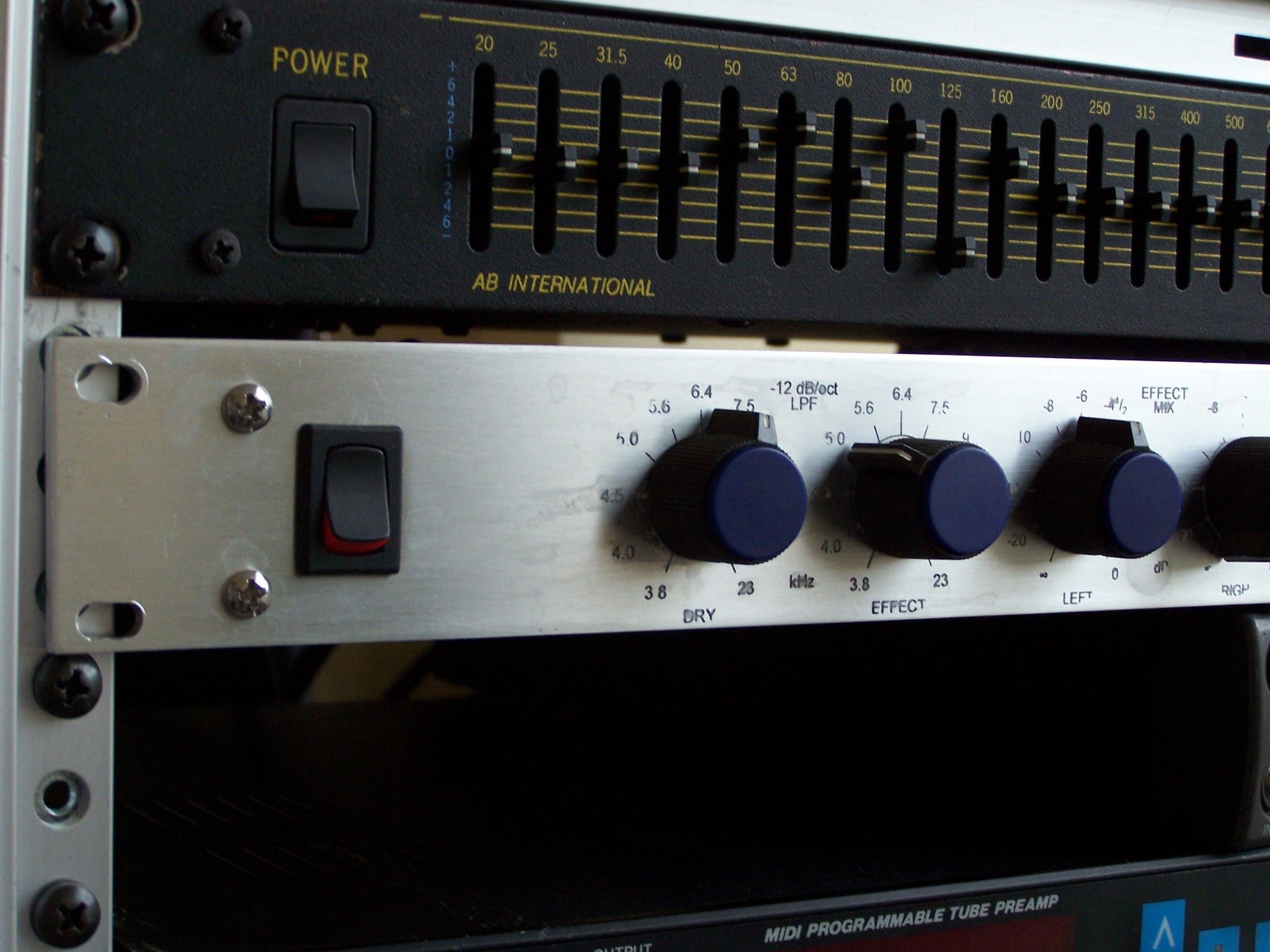
| January 2, 2013 |
Picture of custom faceplate. |
| February 19, 2013 |
Old transformer is gone. |
| March 19, 2013 |
Added missing schematic. |