Variable Speaker Damping Control For
The Alesis RA-100 Power Amplifier


How I turned a Sound Reinforcement and Studio Workhorse
Into a Great Sounding Guitar Power Amp (Too)

Kaz Kylheku <kaz at kylheku dot com>


Date
Notes
July 25, 2011
Initial revision.
July 28, 2011
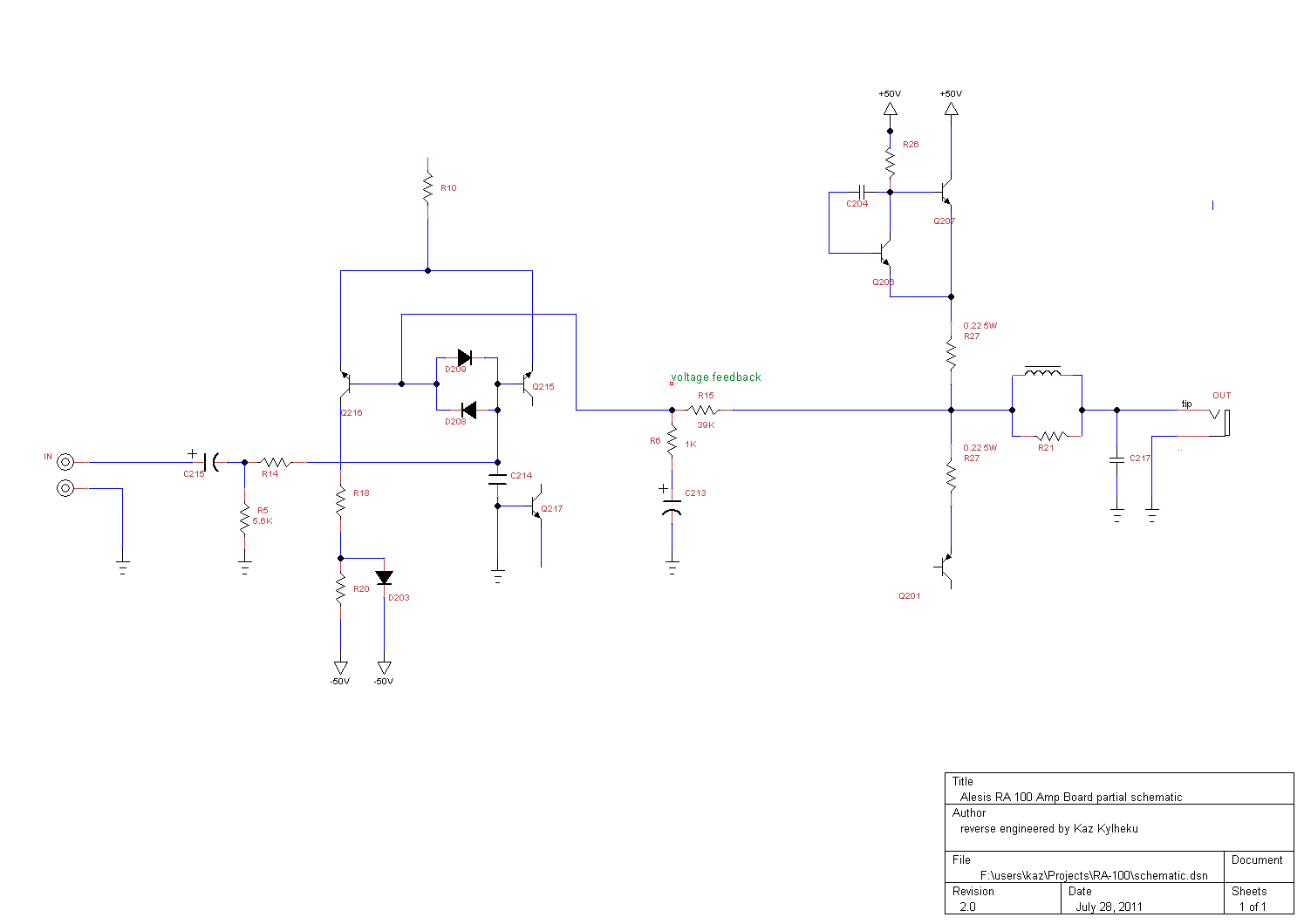
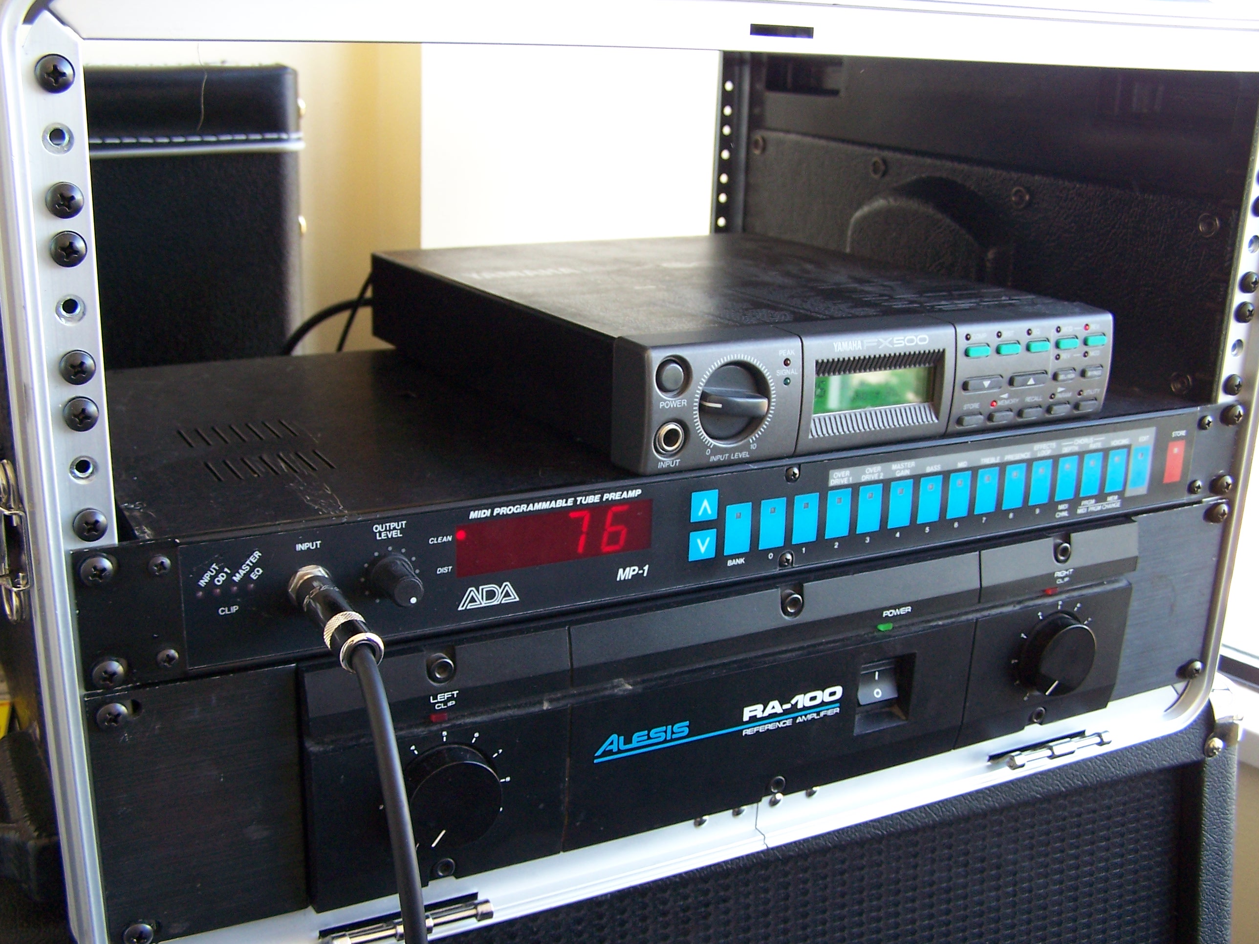
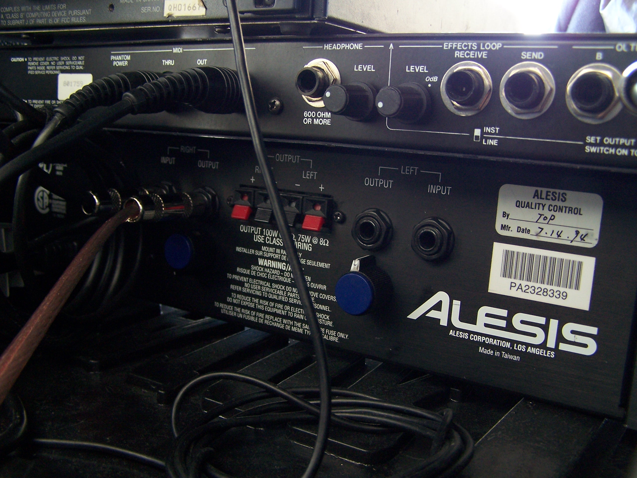
Correction to RA-100 schematic: 
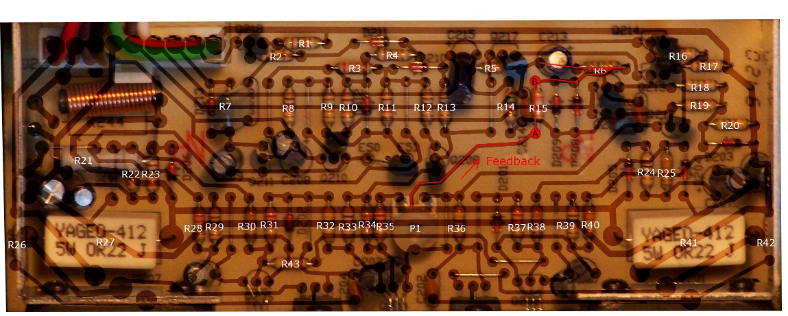
input is not a phone jack.
Grammar corrections.
Added recommendation to use light bulb limiter for smoke tests.
New photo section added at the end.
Aug 28, 2011
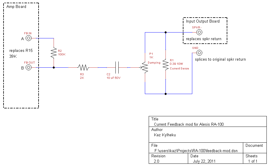
A better circuit version introduced!
Dec 01, 2012
Tweaks for better sound


Introduction

The RA-100 stereo power amplifier was produced by Alesis in the middle to late 1990's, and remains a popular unit on the second hand market, going for anywhere between $80 to $150 dollars. This is very good deal for a nice amplifier, suitable for sound reinforcement, studio monitoring and such.

Some electric guitar players, myself included,  use the RA-100 to power their guitar rig. However, for this use, the RA-100 is unsatisfactory. It is a high fidelity power amplifier with a flat frequency response and a low output impedance which gives it a high damping factor (cited as being at least 200). Such an amplifier has limited use in connection with guitar. It may be suitable for certain clean styles within jazz, using certain kinds of guitars, such as hollow-body or semi-hollow guitars. Of course, it is a good amplifier for acoustic guitars equipped with acoustic pickups.  But for most electric guitar use, if a hi-fi amplifier is used to drive the guitar speaker enclosure, the resulting tone will be described by players as "sterile", "flat", "unresponsive", "brittle", and so forth.    This will be the case for clean as well as heavily distorted tones, and everything in between.

A guitar amplifier has a high output impedance. This causes two things to happen. Firstly, the frequency response is altered to mirror the impedance of the speaker. The resonant frequency of the loudspeaker is emphasized, because the speaker has high impedance at its mechanical resonant frequency, and treble frequencies are also emphasized also because the speaker's coil has an impedance (inductive reactance) which increases with frequency.    This "mid scooped" frequency response, though, is a minor effect because it could be mimiced with careful equalization.    The second effect of a high output impedance is that the amplifier's damping factor is low, and this has an effect which cannot be reproduced with an equalizer. A lower damping factor allows the speaker to resonate more freely. This behavior is necessary in order to produce a warm, dynamic musically pleasing sound from a guitar preamplifier signal, whether it be clean or distorted. The sound will be recognized by guitarists as resembling a tube amplifier: "warm", "rich", "dynamic", "tube-like", or "three-dimensional". Quite simply, the loudspeaker is part of the instrument, and must be treated as a sound production device, not a sound reproduction device.

This article captures my notes from performing a modification to my  Alesis RA-100 which allows both of its channels, via newly introduced rear-panel potentiometers, to have a variable damping factor.  One one extreme of the potentiometer range, the RA-100 retains most of its "hi fi" personality, exhibiting a high damping factor. On the other extreme of the range, the damping factor is  low, and the RA-100 behaves like a very loosely damping guitar amplifier. The range of the control is quite broad, such that the best tone is not necessarily found at the lowest damping position of the knob.

Objective

Early guitar amplifiers used vacuum tubes, and sounded good essentially by dumb luck. Unless additional design measures are taken, vacuum tube output stages naturally have a high output impedance, leading to a low damping factor.

By contrast, transistor output stages have a low output impedance. Furthermore, the output impedance becomes lower (and damping factor higher) when global negative voltage feedback is used to stabilize the amplifier, control its gain, and improve its frequency response and THD values. Voltage feedback means that a small fraction of the amplifier's output voltage is subtracted from the input signal. "Global" refers to feedback which spans multiple amplification stages, such as going from an output stage, back to the first input stage, or one of the early stages. Hi fidelity amplifiers such as the RA-100 typicallly employ global negative feedback.

There is another form of feedback that is used in some solid-state guitar amplifiers: negative current feedback.   Negative current feedback has many of the same benefits as negative voltage feedback. Just like voltage feedback, it stabilizes the amplifier, reduces the gain, and makes the amplifier's gain more linear and free of distortion and noise. Negative current feedback has one crucial difference, however. Instead of lowering the amplifier's output impedance and damping factor, it has the opposite effect of increasing he output impedance and lowering the damping factor! What could be more perfect for guitar.

Voltage feedback and current feedback are not mutually exclusive. They can be mixed and used in combination, a configuration called mixed-mode feedback.

My objective was to add current feedback to my RA-100, to augment its voltage feedback, and use a potentiometer to vary the amount of current feedback from zero to full, to obtain an amplifier which retains most of its original personality, while exhibiting a new flexibility for guitar use.

Investigation

The first steps were to reverse-engineer the RA-100 power amplifier board (it has two of these, one for each channel). Schematics for this amplifier are not available. I wanted to ideally reverse-engineer the entire board and produce a complete schematic. However, I did not perform a complete reverse-engineering, because only a minimal analysis is required to identify the voltage feedback path and augment it (so motivation was lacking).

To reverse engineer the amp board, I took some digital images of the component and copper side.  Using the GNU Image Manipulation Program (GIMP), I manually traced the copper to produce a transparency image showing the traces and pads clearly. This is what the transparency looks like. Note that this is flipped left-to-right, giving us a component-side view.
RA-100 left channel amplifier board pads and traces


This image can be superimposed over the component view, to allow convenient tracing of the circuit:
RA-100 left channel amp board, showing traces.

Note that the RA-100 board gives identifiers to all of the components. There is a D211 diode, a C215 resistor, etc. The resistors are also numbered, but the numbers are not readable for most resistors because they are printed under the resistors. Therefore, I renumbered the resistors and potentiometer. Throughout this guide, the resistor numbers used are these new ones and not the original ones.

Here is the partial schematic, which was produced using the TinyCad program. Someone who is interested in other aspects of the RA-100 can use my images to continue the reverse engineering to produce a more complete schematic:

Schematic


The voltage feedback path goes through resistors R15 and R6 which form a voltage divider that samples 1/40th of the voltage signal.  The feedback path is connected to an AC ground via capacitor C213, which at quiescence is found to have a small voltage of about 42 mV across it, indicating that the feedback destination circuit is slightly positive with respect to ground.

Here is the feedback path on the circuit board:
Feedback path

My approach was to remove the top resistor from the feedback voltage ladder, namely the 39 Kohm R15. This resistor is replaced with a pair of small gauge hookup wires that go to a custom board, where voltage feedback is mixed with current feedback. Note the reference solder pads A and B; they are later referenced in the schematic. Of course, this custom circuit board also provides a resistance in place of the removed resistor.

Design

I implemented the following circuit on a little pre-fabricated PC board:

RA 100 current feedback circuit

Notes on how this circuit works:

I built this circuit on a small pre-fabricated printed circuit board. The board has a 5 pin connector for the two feedback hookup wires, and for the three wires going to the potentiometer. Soldered to the board is a hook-up wire with a connector which interfaces to a splice installed into the RA 100's input output board.

The assembled kit looks like this. Note that this is a slightly older version, which used a different current sensing resistor (the big ceramic block). In the schematic, it is 0.39 ohms, and that is what I use now.  Furthermore, I use separate potentiometers for each channel, not the dual-ganged pot shown in the picture. Also, the red and black wires are soldered close together on my new boards.

RA 100 current feedback kit

Not shown in this picture is the hookup cable which mates with the current sensing cable's connector (the big black and red wires).  This is installed into the amplifier as follows. I unsoldered the speaker return wire (black wire leading back from the speaker return solder pad to the power supply). In place of this, I solderered the hook-up cable's red wire.   The hookup cable's black wire is spliced with the previously unsoldered speaker return/ground wire, and the joint is protected with electrical tape.

Once the above is all ready, it can be installed into the amp. The five connector cable split between the potentiometer and amp board plugs into the little circuit board, and the red/black hookup cable plugs into its mating connector in the amp.

I drilled a 5/8" hole for the potentiometer below the same channel's output jack. This is a nice rear-panel location. It's easy to find in a rack case without shining a light back there or even looknig. Simply put your hands on the speaker cable and feel your way back to the amp, then reach down from there and there is the damping knob for that speaker!

Notes on Feedback

The prior discussion on voltage and current feedback may seem confusing, so here are some clarifying notes.

First of all, to clear up a possible misconception, current feedback does not mean that output current is fed back.  All feedback takes the form of a voltage signal! Current feedback is a small voltage which is proportional to the amount of current flowing through the loudspeaker, whereas voltage feedback is a small voltage which is proportional to the voltage generated over the speaker.   The voltage feedback voltage is obtained by cutting a slice of the output voltage using a voltage divider.  The current feedback voltage is obtained by passing the speaker return current through a current sensing resistor (the big ceramic 0.39K puppy that is built to handle 10W of heat dissipation!)   The current sensing resistor has a small resistance compared to the speaker, and so it does not add an appreciable resistance to the load. Approximately the same amount of current flows through the speaker whether or not the sensing resistor is present.  A small voltage develops across the current sensing resistor, and this voltage is the basis of the current feedback signal.

Why does current feedback promote lower speaker damping? The reason is fairly intuitive.  Lower damping occurs because when the speaker wants to dump flyback current back through the amp, that current flows through the current sensing resistor, and it is opposite in polarity to the current which put the speaker in the position from which it is returning. For instance if we put a positive voltage on the speaker causing the cone displace, then when the speaker's suspension wants to return the cone, the voice coil wants to generate a negative flyback voltage. This voltage generates current in the current-sensing resistor, which turns it into current feedback that is subtracted from the input! But subtracting a negative means adding! If something is added to the input, the output voltage rises, fighting the speaker's flyback voltage! The speaker "sees" this as a high(er) impedance, which causes it to be less able to work off energy electrically.

Why does current feedback promote a "mid scooped" frequency response? That is also easy to understand. The speaker already has a "mid scooped" impedance curve. It has a high impedance at speaker resonance (typically somewhere between 70 Hz and 100 Hz for a guitar speaker). It also has a rising impedance with increasing frequency because it contains an inductor (the voice coil). Inductors impede the flow of alternating current: the higher the frequency, the greater the impedance.  Now, speaker impedance reduces the current that flows through it, resulting in a smaller amount of negative current feedback. Less negative feedback of any kind translates to more gain.   So the amplifier adds gain in proportion to the speaker's impedance, emphasizing the resonant frequency, and treble frequencies.  This mid-scooped frequency response is perfect for guitar. It counteracts the frequency response of pickups, which emphasize the middle, and sounds great for distorted sounds also, reducing their "honkiness".

Why does negative feedback reduce gain? This can be shown with some very simple mathematics.  Suppose we represent the amplifiers open-loop gain with the variable G. This is the gain without any feedback and is some positive number like 100. If G is 100 then without any feedback, the amplifier amplifies 0.1 volts into 10 volts (0.1 x 100 = 10).  Now take the variable F to represent the amount of feedback, expressed as a fraction of the output. For instance, if F is 1/100, then it means that 1/100th of the output voltage is turned into negative feedback, subtracted from the input. Let the variables Vi and Vo represent the input signal voltage and the output signal voltage.   The feedback voltage is then  FVo: the feedback fraction times the output voltage. We can then write down this equation for the overall behavior:

   Vo = G (Vi - FVo)

That si to say, the output voltage is the input voltage minus the feedback signal (F Vo), multiplied by the amplifier's gain G.  The trick is now to get the variable Vo by itself:

  Vo = G Vi - GFVo

  Vo + GFVo = GVi

  Vo(1 + GF) = GVi

  Vo = GVi / (1 + GF)

But of course, without any feedback, the relationship between Vo and Vi is, of course, just this: voltage out is voltage in times gain:

  Vo = GVi

So what feedback F does is reduce the gain by a factor of   1 / (1 + GF).   Note how if we set F to zero, this reduces to 1, and so we get Vo = GVi.

Example: if the open loop gain is 100, and the feedback is 1/100, what is the effective gain?  It is G/(1 + GF)  or 100/(1 + 1/100 x 100), which is 100/(1 + 1) = 50.  The gain is cut in half by the feedback.

Construction Notes

Here is what the circuit board looks like that I used, shown from the copper side, with the component locations superimposed:

PC board

The 5-pin connector's yellow and blue wire are the voltage feedback in and out lines, respectively, connecting to points A and B on the amplifier board. The red, white and green wires go to the potentiometer. White is wiper, red is hot, green is ground. The thick gauge black and red wires are the speaker current hookup wires. Red is speaker return, black is ground. Two jumper wires are used in the layout.

I got away with using 22 AWG wire for the high-current hookups.

Tip: keep the hookup wires away from the transformer or they may pick up hum, causing the modified channel to have a faint hum independent of input volume.

Test Procedure

  1. Perform a smoke test. Install everything and turn on the amplifier, with inputs and outputs disconnected (no speaker or preamp). Listen for any popping sound, and watch for signs of smoke. If anything burns or blows, the test fails.  A useful device for smoke tests is a lightbulb limiter. If you have one, use it. If not, build one.
  2. Check that the large output transistors (big black suckers on the heat sink) are not getting hot, and they stay cool for several minutes. If they get hot, the test fails.
  3. Measure the AC voltage across the speaker terminals. It should be zero. If there is a voltage present, the amp is probably oscillating and the test fails.
  4. Plug in input and a speaker, and play. If no sound comes out, fail.
  5. If sound comes out, test the damping control. It should have an obvious effect on the amp's gain. At the low gain position, low speaker damping should be heard, and a richer bass and treble response.
  6. Continue to monitor the output transistors for signs of excessive heating.

Tips

You need numerous tools: wire cutters, combination pliers, soldering iron, soldering pump, soldering wick, multimeter, screwdrivers, an allen key, ...

Be gentle with the RA-100's circuit boards; they seem fragile. Relieve the force when plugging and unplugging connectors. Don't flex the board!

Solder pads within the RA-100 lift very easily. When soldering or desoldering, do not overheat the pad. If things are not going well, then let that joint cool while turning your attention to another joint.  The leads of many components are bent to acute angles, making it impossible to suck or wick all of the solder if you leave them in that position. If you pry at these to straighten them, you will lift the pad, due to the solder remaining underneath. The trick is to get these terminals into straight position without lifting the pad, and this should be the first thing you do before you remove any solder. Heat the joint until the solder liquifies, and continue to apply heat while with the other hand using a small screwdriver to pry the terminal up. Don't apply heat for too long. It may take several tries to get it straight.  Once the terminals are vertical, then you can suck away the solder with your solder sucker. The part should now come out easily, and the solder pads stay put.

The speaker return ground wire may be reluctant to come out, because the braided filaments are full of solder, making it too thick to pass through the hole. What you can do is take some pliers and squeeze the tip of this wire from several angles to make it smaller, so it fits through the hole.

If a component is reluctant to come out because of small quantities of solder remaining on the the terminal or in the hole that are difficult to wick away, then gently push down on that terminal with the soldering iron. As it the terminal heats up, the solder will soften and the terminal will give way to your pressure, sliding into the hole. Push it all the way down to the pad, then remove the iron. The component should remove easily after that.

I placed my circuit boards on the floor of the amp by making four feet for them out of glue from a glue gun.  I covered the solder joints with a piece of electrical tape --- I wouldn't want some stray piece of metal shaving to bridge a contact between a solder joint and chassis.

Use plastic ties to bind your hookup wires together to keep them neat.

To drill a hole for the potentiometer, first make a pilot hole with a small-size drill bit. Work your way through increasing drill bit sizes until you reach the desired size. For my pots, I had to go all the way up to 5/8". Aluminum is soft and easy to drill, so go easy. Use a small round-file to clean up the hole if necessary, and be sure to vacuum the inside of the amplifier of all aluminum millings. They are conductive!

New Circuit Version!

I no longer use the circuit described above, because the following circuit is far superior:
schematic

Note that there is a 50K potentiometer used, and it is in a different configuration. The inessential coupling capacitor is also gone, and there is a different configuration of resistors. The current sense resistor is the same 0.39 ohms, though.

This circuit is better because when the potentiometer is turned all the way left, it allows the Alesis to have something very similar to its original personality. Because in this position there is still some current feedback, the resistance is made smaller: 30K versus the original 39.

As you turn the knob to the right, the amount of voltage feedback slowly decreases, and there is a moderate increase in gain. Current feedback increases only slightly. Then at about three quarters of the way, current feedback starts to increase greatly, and the gain drops off sharply. This last 20-25% of the knob controls most of the current feedback action. At the far right, current feedback is at maximum (even more than in the previous circuit, because the series resistor changed from 2K to 1K). In this extreme position, the voltage feedback resistor ratio is about 80K to 500 ohms. (In the old circuit it was 100K to 600 ohms, so the new circuit hits about the same minimum voltage feedback, but a greater maximum current feedback.)

The reason I designed the new version of the circuit is that the original was inadequate for heavy distortion tones. The speaker damping was too loose, causing palm-muted notes around the speaker's resonant frequency to have tremendous thump compared to other notes. Furthermore, the emphasized frequency response too harsh. The tone was useable at practice volumes, but when turned up quickly became brittle, flabby and lacking in focus and clarity.  (However, for cleans, bluesy overdrives and crunch sounds, it sounded fine.) There was no adequate way to adjust it because turning down the current feedback did not bring back voltage feedback, leaving the amp inadequately controlled.

With this new circuit, there is a lot more control, making it possible to find great sounding tones in the intermediate positions of the knob. Tight sounds can be found, which are still loose enough to breathe, so to speak.

Tweaks for Better Sound

Recently I have been overhauling the whole guitar rig, and one of the pieces that went under scrutiny has been the RA-100 again.

I decided to investigate the bias of the power section. I hooked it up to a 10 ohm, 100W load resistor and fed it a 10 Khz sine wave. Looking at the oscilloscope trace of the amplifier output, I was surprised to discover that both channels showed a little bit of a crossover notch: evidence that the amp is biased cold, only class B. So on each channel, I turned the bias potentiometer until the notch disappeared and then just a tiny bit more. It was not a big notch. Just a small kink in an otherwise seemingly continuous curve. Clearly, negative feedback corrects for crossover quite well.

Still, as a result of the adjustment, the sound quality has improved. It is somehow clearer, more transparent. Is it confirmation bias? Well, after several weeks, I'm getting consistently good sound, without experiencing a "bad tone day". Negative feedback or not, audio amps should be biased into class AB operation, not class B.

Another thing I have done, which is related to the feedback mod, is to clamp ferrite chokes around the speaker return lines. Voltage feedback is protected from the entrance of RF, because it is behind an inductor with a ferrite core, and a shunt capacitor. But the feedback mode adds raw speaker current feedback to the amp: a passive resistor network which obtains a signal directly from the speaker circuit, bypassing the choke. It behooves us to put something there to block RF. The chokes seems to have improved the sound quality also.

Pictures

Here are some pictures of the Alesis in the rack case. The rear picture shows the blue current feedback knobs, one directly under each output jack. Internal pictures of the mod coming soon!
Amplifier in rack case

Amplifier in rack case